TASKLED - Smart LED drivers
home > products (b3Flex)
b3Flex Buck Driver, 3Amp Maximum (user configurable output current)
Perfect solution for driving series strings of power LEDs such as:
- XM-L
- P7
- MC-E (parallel die)
- XP-G/XR-E
b3Flex (Hardware specifications/features):
- Microcontroller based constant current regulator.
- Ships configured for 500mA current limit.
- User reconfigurable to 500/750mA*/1000mA/1500mA/2000mA/2500mA or 3000mA at any time.
- Ships with UI-UNI4 firmware.
- 3 user configurable voltage trip points to set independent Medium, Low warning levels and Cutoff, useful to protect rechargeable batteries from overdischarge (Refer to technical section).
- STAT output. If an optional 3mm or 5mm status LED is connected, the user can configure the status LED to warn when the voltage reaches Medium (status LED lights constant) or Low (status LED flashes). With on-board 100 ohm series resistor.
- Onboard pullup resistor on switch input to provide reliable performance of external momentary action switch when used with longer wires.
- Temperature monitoring of driver board. If closely coupled with the light's body, it can be user configured to force the current output to reduce. Optional trip points of 50, 60, 70, 80, 90C or off.
- UIB2: Bike optimized, Choice of 2 level (duomode), 3 level (trimode or threemode) or 5 level (multimode) operating modes.
- UIF: 8 level dimming, fixed lighting use optimized.
- UIP: 5 level dimming, flashlight use optimized.
- Non-volatile storage of brightness level.
- Draws ~200uA when in 'sleep mode'.
- >85% efficiency (see technical section).
- Can drive up to 23V of series connected LEDs (from minimum input = (output voltage + 1.1V)).
- Input operates from 4V to 25V. Being a buck converter, input voltage must be greater than output voltage - see the b3Flex technical section (manual) for specific information. Do NOT use more than 5 series connected li-ion cells.
- Protected against reverse polarity connection (low loss FET), output open circuit and output short circuit.
- Shielded inductor to reduce radiated EMI.
- Board is 1.0" in diameter, 0.30" thick (tallest components on both sides + board thickness).
*750mA option introduced in V1.3 of the firmware (April 14, 2012)
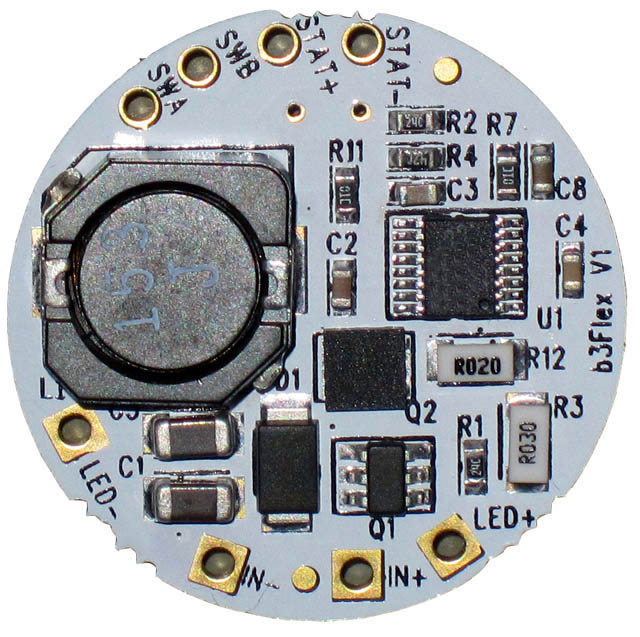
Following is a picture of the top of the new b3Flex driver. The outlined polygon area on the left side (surrounding the TaskLED (C) 2012 etc) is for attaching to a heatsink when the b3Flex is run at higher output currents (>1.5A). It is recommended to use 2 part thermal epoxy such as Arctic Alumina to mount the b3flex to the heatsink or optional shim. Please refer to the b3Flex technical section for operating and wiring details.
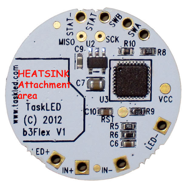
Following is a picture of the bottom of the b3Flex driver.
home | products | technical | order products | contact
©2026 TaskLED. All Rights Reserved.